
The XCircuit Tutorial
Table of Contents
Getting started
Welcome to xcircuit, the circuit drawing program by Tim Edwards. In order to
get the most out of this page, you should have already downloaded, compiled,
and installed the xcircuit program and its libraries.
First, start xcircuit without any parameters: xcircuit
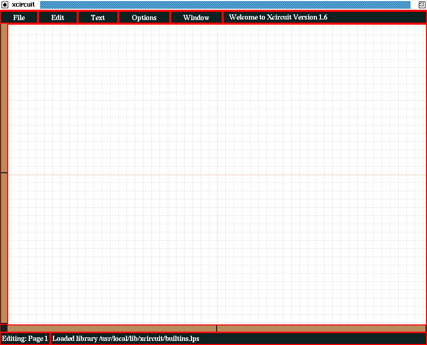
The features of the xcircuit window are as follows:
- Along the top of the screen are buttons for pull-down menus called "File",
"Edit", "Text", "Options", and "Window".
- At the top, beside the menu buttons, is a welcome message in the message
window telling you the version number of the program (Version 2.0).
- On the bottom left is a message window telling you that you are currently
editing "Page 1".
- On the rest of the bottom is a message window telling you that xcircuit
has just loaded the library "/usr/local/lib/xcircuit/builtins.lps" (this
may be in a different directory if xcircuit has not been installed in the
default directories). This message will disappear after about 10 seconds.
- At the left and along the bottom are two scrollbars which report the
position of the drawing relative to the main window, and can be used
to reposition the drawing by clicking on the bar with any mouse button.
Note: Due to the length of time necessary to refresh the drawing
window, the scrollbars cannot be "dragged".
- In the center is a white drawing area with lightly-colored grid and
axis lines.
There are two types of mouse button-pushing used in xcircuit. When a button
is pushed and released quickly, I will call it "tapping". When a button
is pushed and held down, I will call it a "pressing". Since pressing
a button is usually performed in order to move objects around on the screen,
I will sometimes refer to it as "dragging" the object.
Note: Xcircuit does not use double-clicking.
Acquaint yourself with the arrangement of menu buttons and pulldown menus.
- Press the button labeled "Options" with mouse button 1 and hold down
the button while you drag the cursor around with the mouse.
- Keeping the mouse button pressed down, move down to the "Elements" button.
Each button will highlight as you pass through it.
- Put the cursor on top of the arrow icon at the right side of the "Elements"
button. You should see a secondary menu titled "Elements" pop up. The
title is the topmost entry of the menu. It has no function and does not
highlight when the cursor is overtop it.
- Keep moving down to the "Color" button and again move the cursor over
the arrow icon. The third and final menu of colors will pop up. Note
that one item, "Inherit Color" has a check mark on it. The check mark
denotes that this entry is the current default color.
- Move down to the purple color button and release the mouse button there.
The menus will disappear. You have just changed the default drawing
color to purple.
- Repeat the procedure up to step 4. When you enter the "color" menu you
will see that the purple color button is now checked, showing that
purple is the default drawing color.
Throughout the tutorial I will refer to the menu items using the pulldown
hierarchy, with an arrow ("->") wherever you need to go to a submenu. So
the "Inherit Color" menu item would be referred to as
"Options->Elements->Color->Inherit Color".
Now that you understand the function of the menu buttons, it's time to learn
how to draw something. The simplest and most common thing to draw in xcircuit
is a polygon.
- Tap mouse button 1 anywhere in the drawing area and release it
immediately. If you wait too long to release the button, xcircuit will
interpret it as trying to "grab" an element on the screen, and nothing
will happen (because there aren't any elements yet to grab).
- Move the cursor around the screen. A purple line (because you chose
purple to be the default color in Task 2) will appear between the
origin point and will track with the cursor.
- Tap mouse button 1 again to finish a line segment. A new line
will begin at the point the first one left off. Do this several times
to form a polygon. Finish the polygon by tapping mouse button 2.
- Repeat steps 1 through 3 but finish by tapping mouse button 3.
The line you have just created will disappear. You have just
cancelled the operation.
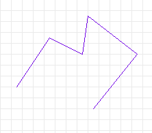 A purple polygon
For most operations in xcircuit, tapping mouse button 1 will begin or
continue an operation, tapping mouse button 2 will finish it, and
tapping mouse button 3 will cancel it. The behavior can be slightly
different depending on the circumstance, and the behavior for pressing
buttons 1 and 2 is very different, as demonstrated in Tasks 4 and 5.
mouse button 1 does have one very different function than that described
in the last task. It can be used to "grab" hold of an object for moving.
- Press mouse button 1 close to a line of the polygon you just
drew. Hold down the button. The line should turn gold colored,
indicating that it has been "selected". If instead nothing happens,
then the cursor is too far away from the line. Releasing the button
releases the object.
- Try grabbing and releasing the polygon from different distances to get
a feel for how close you must be to the object in order to grab it.
- Now grab the polygon, and with the mouse button held down, move the
cursor across the screen. The polygon will follow the cursor. This
is how you move an object in xcircuit.
mouse button 2 also has a selection funtion; in fact, it has two of
them. In the normal drawing mode, it can be used to select objects for editing
or changing properties. In this task you will use mouse button 2 to
select the polygon you just created in order to make it a dashed line.
- Select the object by tapping mouse button 2 with the cursor near
to the object. The object will turn gold, indicating that it has been
selected.
- Tap mouse button 3, and the selection will be canceled.
- Investigate the other form of selection by pressing mouse button 2
starting below and to the left of the polygon, and dragging the cursor
to the top and right of the polygon. A green box will follow the
movement of the cursor.
- When the box completely surrounds at least one of the endpoints
of any line segment of the polygon, release the button. The polygon
should be selected.
- Click mouse button 3 to deselect the object.
- Repeat steps 3 through 5, noting that if no endpoint of the polygon
is contained within the select box, then the polygon will not
be selected.
- Select the polygon but do not deselect it.
- Go to the "Options->Elements->Border" submenu and select option
"Dashed". When you release the button, the polygon will be drawn
in dashed lines, and it will no longer be selected.
- Experiment with the different Colors, Fill-styles, and Border-styles
available in the menus. Some of the many varieties are shown below.
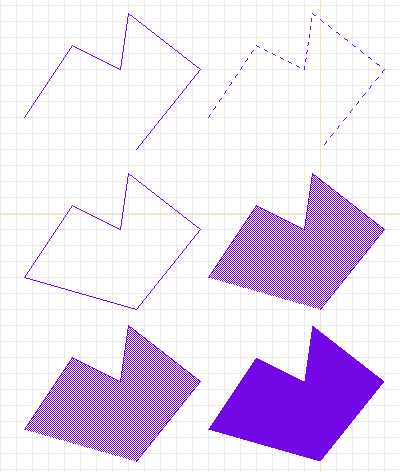 More purple polygons.
Top left: original.
Top right: dashed.
Center left: closed. Center right: stippled
(50% stipple).
Bottom left: opaque stippled. Bottom right:
filled solid.
Xcircuit has multiple pages. There are two ways to change the current
drawing page, from a keyboard macro convenience function, or from the
menu.
- Select the menu item "Window->Goto Page->Page 2". The polygon
you just drew on Page 1 will disappear, and you will be on a
clean page, with the bottom left-hand window saying that you
are editing "Page 2".
- Go back to Page 1 using the keyboard macro: With the cursor
in the drawing area, press the "1" key. You will be back on
page one.
- Keys "1" through "9" and "0" will get you instantly to pages
1 through 10, respectively.
- End this task on Page 2, which is currently empty.
Another common task in xcircuit is to grab an object from the object
library and place it on the drawing.
- Select the "Window->Show Library" button from the menu, or press the
"l" (that's "ell" as in "library") key in the drawing window. Note
that the menu button has
"(l)" written after "Show Library", indicating that the keyboard
macro "l" has the same function as the menu button. Generally,
keyboard macros, once memorized, are more convenient to use than
their menu button counterparts. Almost always, the letter or symbol
used for the macro is meaningful and easy to remember (like "a" for
"arc", "s" for "spline", "p" for "pan", "c" for "copy", etc.).
- A page will appear, showing a number of circuit objects in the
built-in object library.
- Grab one object by moving the cursor over top it and pressing and
holding mouse button 1. As soon as the button is pressed,
the object library will disappear, and you will be dragging the
object around Page 2, from which you called up the library. When
you release the button, the object will be deselected. Place it
away from the polygon you drew in the previous tasks.
- Select the object by tapping on it with mouse button 2.
Try changing the border style to dashed. You will see that
nothing happens. This is because object instances from the
library are made up of basic elements like polygons,
arcs, and splines, but they are composite objects which
do not have properties like "Fill-style" and "Border-style".
However, object instances do have the property of color, and
also the property "size" which simple elements like the polygon
do not have.
- Select the object again (if you have not already done so), and
then select the menu item "Options->Elements->Object Size".
- A window will pop up asking you for an object size. Place the
cursor somewhere inside the popup window and change the default
size of "1.00" to "1.5".
- Press the "Okay" button. The popup window will disappear and
the object will now be 1.5 times its original size (that is
to say, its length and width will each be 1.5 times their
previous value).

Part of the default circuits built-in library.
As mentioned above, keyboard macros are generally easier to use than
their menu-button counterparts. You will create an arc in both fashions
to show the difference.
- Select the menu item "Edit->Make Arc".
- The information window at the bottom will say "Click button 1
and drag to create arc".
- Place the cursor where you want the arc center to be and press it.
While holding it down, drag the cursor around the screen. An arc
will follow the cursor.
- Release the mouse button. You will now be editing the angle of the
first endpoint. If you just want a circle, tap mouse button 2
to end. If you keep pressing mouse button 1, you will be
able to edit, in turn, all the properties of the arc such as
endpoint positions and ellipse axis.
- Now, create an arc by tapping the "a" key while the cursor is in the
drawing area. The main difference is that mouse button 1 is
not held down while you form the radius of the arc. Otherwise,
the arc can be edited as before.
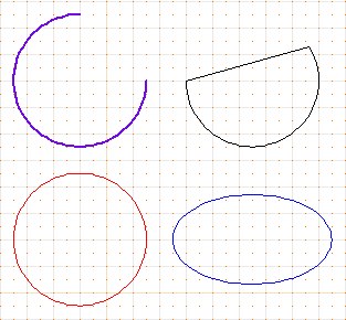 Some differenct arcs.
Top left: linewidth of 1.5, first endpoint at 90 degrees.
Top right: closed arc.
Bottom left: red circle.
Bottom right: blue ellipse.
- Pan the screen to be centered on the arc by placing the cursor close to
the center of the arc and tapping the "p" key.
- Pan the screen by selecting menu item "Window->Center Pan" and then
tapping mouse button 1 on the point of the drawing area that
you want to be the new center of the screen.
- Tap the "Z" and "z" keys to zoom in and out, or select the menu items
"Window->Zoom In" and "Window->Zoom Out". Note how the scrollbars
on the side and bottom of the screen change with the scale of the
drawing.
- Pan the screen by tapping any mouse button on either of the scrollbars.
Note how this function is similar to the "Pan" function.
- Zoom to a selected area of the screen by making a green selection box
like you did in Task 5, step 3. However, instead of releasing the
button in order to make the selection, type the "Z" key while the
mouse button is still pressed down. The screen area will zoom to
the area of the green box.
- Alternately, choose "Window->Zoom Box" from the menu. Then press
any mouse button and drag to generate the green selection box. When
the button is released, the screen area will zoom to the area of the
green box.
- Clear the current page by choosing the menu item "File->Clear Page".
There is no keyboard macro for this command, to prevent accidental
erasure of the screen (which cannot be undeleted).
- Grab several objects from the library (see Task 7) and place them
on top of each other in the middle of the page.
- Decide on one object which you will move, leaving the others where
they are.
- Now press mouse button 1 as if you were going to select the
object you want to move. Because the command is ambiguous---the
program doesn't know which one or ones of the objects you really
want to select---the program will query you one by one for which
objects you want to select.
- One object will turn blue, the cursor will become a question mark,
and the information bar at the bottom will read, for example,
"Click to accetp/reject: 1 of 3" if the program found three
objects under the cursor. Release the mouse button at this
point.
- If the object that you want to select and move is colored blue,
click mouse button 2. If an object that you don't
want to select and move is colored blue, click mouse button
3.
- When you have chosen or rejected each of the objects, the cursor
will become a circle. You may now press and hold mouse button
1 and continue with the intended move.
- Try this several times to get used to it.
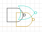
Three objects simultaneously selected.
The gold-colored gate has already been selected; the program is now prompting
the user for confirmation to add the blue-colored object to the selection.

Message window when selecting multiple objects.
Since the main purpose of xcircuit is to create publishable-quality picutures,
it is necessary to understand a little bit about the PostScript output which
it writes. First I will show you how to save and load a file.
- Choose a page which you have been drawing on, or create a drawing to
save.
- Select the menu item "File->Write Xcircuit PS". You will get a popup
window that looks like the figure below.
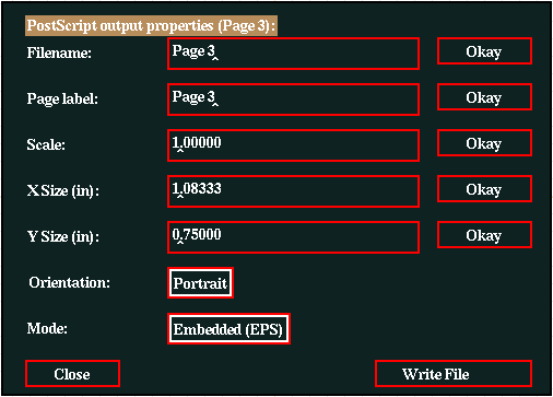
The file properties popup window.
- If you tap the button labeled "Write". You will get a message in the
bottom message window saying "Warning: Enter a new name". Nothing
has been written at this point.
- Change the filename. Move the cursor over the window containing the
filename. Delete the current file name and type in a new one.
When you are done, either hit the RETURN key or tap the
button labeled "Okay" (both actions have the same effect).
- Important note: If the name has no extension, an
extension ".ps" will automatically be added when the file
is written. If an extension, for instance ".eps", is written
in the filename, then it will be used.
- When you change the filename, the page label will be changed to
match the filename, and the bottom left-hand message window will
now say "Editing: " followed by the page label name, followed by
the page number in parentheses.
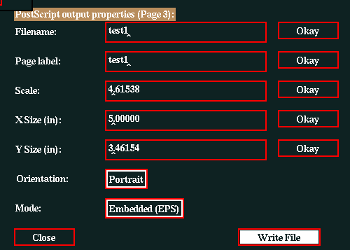
Changes to scale and filename.
- If the filename you chose already exists on the disk, the button
which previously was labeled "Write File" will now say "Overwrite
File", the computer will beep, and the bottom message window will
say "Warning: File exists".
- Tap the button labeled "Close". The window disappears; because
you did not tap the "Write File" button, nothing was written,
although the filename change has been registered.
- Select "File->Write Xcircuit PS" again to bring the window back.
This time, tap the "Write File" button. The file will be written
to the disk current directory, and the button which previously
said "Close" will now say "Done".
- The file which has just been saved is already in a PostScript format.
You may view it with any PostScript previewer (ghostview is recommended).
- Go to a new, unused page.
- Select menu item "File->Read Xcircuit PS". You will get a screen that
looks something like the following:
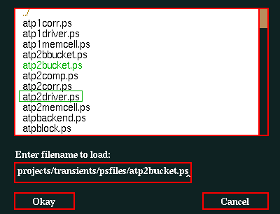 The load-file popup window.
- If the file list is larger than the window, you may scroll up and down
the list by clicking mouse button 1 or 2 on the
scrollbar at the right side of the window and dragging it up
and down.
- A green box will be drawn around each filename as your cursor passes
over it.
- Find the file that you just saved in the last task. When the green
box is over this filename, tap mouse button 1. The filename
will turn green, and at the same time will be copied into the
text edit box.
- Tap the "Okay" button to load the file.
- If you do not wish to use the scrolling menu, you may type the filename,
with or without the ".ps" extension, in the text edit box,
followed by the RETURN key or tapping the "Okay" button.
- Selecting a directory name in the file list box, including "../" for
the directory one level up, will go to that directory. Entering a
directory name in the text edit box followed by the RETURN
key will also go to that directory.
- If you know where the xcircuit source is kept, then select the
"File->Read Xcircuit PS", go to the source directory, go to the
"examples" directory, and load one of the example files, such as
"vcoblock.ps".
Xcircuit has a very complicated interface for entering text, which allows
you to change fonts and font styles within a string, make overlines and
underlines, and subscripts and superscripts.
- Go to a new, unused page.
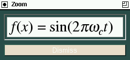
- Let's say you want to type in a fairly complicated expression, like
"f(x) = sin(2*pi*omega_c*t)" (except with Greek letters, of course).
- If you've read your TeX manual thoroughly, and understand all the finer
points of mathematical equation typesetting (if you haven't, you should),
then you know that all the variables should be in italic type.
- Select menu item "Text->Style->Italic". The default text font is now
italic style.
- Select menu item "Text->Font->Times Roman" if it is not checked already.
The default text font is now Times Italic (Times font + Italic style).
- Select menu item "Text->Make Label" and click on mouse button 1
anywhere in the drawing area.
- Alternately, you can just tap the "t" key in the drawing area.
- The green line marks the pointer position, and the "x" marks the
origin (justification) of the text.
- Select menu item "Text->Justification->Middle Justified". You will
see the green "x" move to the center of the line, showing that the
text is vertically centered on its point of origin.
- Alternately, you could type keypad key "6" (on some systems,
Shift-keypad 6) to get center-left justified text.
- Type "f". In the bottom message window, the letter "f" and a vertical
bar "|" appear, showing what's in the string relative to the text
cursor.
- Select menu item "Text->Insert->1/4 Space". This is the proper thing to
do for "italic correction", an extra bit of space necessary after an
italic character followed by an upright character, particularly tall
ones such as "f" and "t" which lean leans rather far to the right of
their character bounding boxes.
- Select menu item "Text->Style->Normal".
- Type "("
- Select menu item "Text->Style->Italic".
- Type "x"
- Select menu item "Text->Style->Normal".
- Type ") = sin(2"
- Select menu item "Text->Style->Italic".
- Select menu item "Text->Font->Symbol".
- Type "\". A page with the 256 character encodings for the
Symbol font will appear, replacing the current page, as
shown in the figure below.
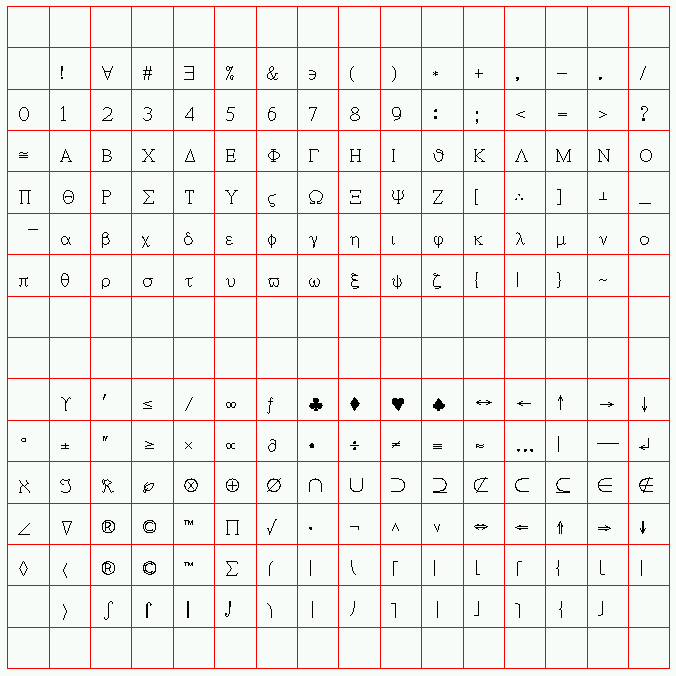
- Click on the "pi" symbol. The screen will immediately
return to the original page, with the "pi" added to the
text line.
- Type "\", then click on the "omega" symbol in the encoding
vector.
- Select menu item "Text->Font->Times-Roman"
- Select menu item "Text->Style->Subscript" (or keypad-minus)
- Type "c"
- Select menu item "Text->Style->Normalscript" (or keypad-enter)
- Type "t"
- Select menu item "Text->Insert->1/4 Space" for another italic
correction.
- Select menu item "Text->Style->Normal".
- Type ")"
- Before typing <RETURN> to complete the text, use
the left- and right-arrow keys to move the cursor around inside
the text string. Note how font- and style- changing commands
embedded in the text string can be seen in the message window.
Their position relative to the text cursor is important when
anticipating the effect of deleting (<DELETE> key)
a text command.
- Yes, this is very complicated, but it is also very powerful.

Above: The text figure created in the task.
Below: The PostScript output of the same text from xcircuit.
Typographical Note: ISO-Latin1 encodings define the Greek character "mu"
(µ) to be used for the symbol "micro", which naturally is used often in
circuit schematics. This differs from the Symbol font "mu" in that it matches
the style and properties of the font in which it is defined. Thus, it is
possible to get a Helvetica "mu", a Times-BoldItalic "mu", etc., something
which is virtually impossible to do even in LaTeX(*).
Due to the font size and style matching, this is always preferable to the
Symbol font "mu". To get the ISO-Latin1 "mu" character, (while entering or
editing text) choose Text->Encoding->ISO-Latin1 from the menu, then
either choose Text->Insert->Character or type "\" at the text cursor,
then select the "mu" character from the character array.
Curve drawing is a useful feature of most capable drawing programs. The
concept of paths is a powerful aspect of PostScript which is not
usually found elsewhere. Path definitions are used to create a single
entity out of a string of curves, arc segments, and lines. The resulting
entity has its own color, fill styles, and border styles.
- Go to a new, unused page.
- Type "s" to start a curve (you can think of "s" as standing for
"spline", although these are Bezier curves, not splines, or you
can just think of the curvy "s" shape. The key "c" is reserved
for copying). The first thing you will see is two dotted lines
ending in little "x" marks. These are the curve control points.
- Move the cursor around. Right now you are positioning the
end of the curve but have no control over the control points.
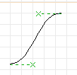
- Place the curve endpoint. If you are satisfied with the shape
of this curve, you can tap mouse button 2 to finish
the curve and quit. However, we'll say that you have more to
do to this curve, so tap mouse button 1 instead.
- You get a message saying "Adjust control point", and the cursor
moves overtop the nearest "x" mark. Now when you move the
cursor, you change the shape of the curve.
- Move the control point two grid blocks to the left of where it
started (make the control line horizontal with a length of
4 grid blocks).
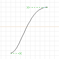
- Click mouse button 2 to finish the curve.
- Now we will make a simple path. But it takes more than one element
to form a path. Put the cursor over the curve and tap the "c"
key.
- When you move the cursor, a copy of the curve will follow you.
- While you are dragging the curve copy, flip it by tapping the
"f" key and then the "F" key (one horizontal plus one vertical
flip).
- Place the curve with its endpoints overtop the original curve.
The result should look like the figure below.
- Select both curves by tapping mouse button 2 on top of
each one, or by forming a selection box (see Task 5).
- Tap the "j" key in order to "join" the two curves into a single
path.
- If you now move or select the path, you will find that both
curves act as a single entity.
- Select the path and then select menu item
"Options->Elements->Fill->(black box)". The path will then
become solid black. If you color it blue, it will look something
like the right side of the figure below.

Curves and paths. Left: The curve has been copied and flipped.
Center: The two curves are placed together and joined into a path.
Right: The path is filled and colored as a single entity.
- Clear the current page (menu option "File->Clear Page") or go
to a new, unused page.
- Start a box with the "b" key (this is a convenience for
drawing rectangles and squares).
- Click mouse button 2 to finish the box.
- Select the box and choose menu item
"Options->Elements->Fill->(black box)", where the "black box"
is the first menu item in the list. You will now have a black
box. (note that to select the box, the cursor must be near the
edge of the box, not in the middle).
- Select the box again and choose menu item
"Options->Elements->Color->(orange box)". You will now have
a solid, orange box.
- Go to the built-in library ("l" key) and bring back a circuit
object (say, a "nand" gate).
- Place the gate on top of the orange box.
- Make a copy the box ("c" key) and place it beside the first.
mouse button 2 ends the copy command.
- You will notice that the library object suddenly disappeared.
This is because the "copy" command moved the orange box
to the end of the drawing list. Because it is drawn after
the library object, the library object is hidden underneath.
- To get the library object on top again, select everything in the
area of the orange box by forming a selection box around the
orange box (mouse button 2). Tap the "X" key (Shift-X)
to exchange the drawing order of the two elements. The
library object will now be visible on top of the orange box.
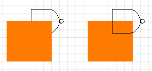
Over- and Under- arrangements of elements.
One of the most powerful aspects of xcircuit is its ability to deal with
objects on a hierarchical level. Circuits in particular are highly
structured. Often it is desirable to draw a subcircuit and use it
several times. It is much more efficient to draw the subcircuit and
create a user object from it rather than to copy all the
separate elements of the subcircuit every time you want a copy.
This is also true of new circuit components.
Say we wish to create a new circuit component, a dependent current
source.
- Clear the current page or go to a new page.
- We want the dependent current source to look something like the
independent current source (isource) in the builtin library file.
Go to the library and bring back an "isource" object for reference.
- Draw a polygon, as in Task 3. Make it diamond-shaped and three
grid spaces high, two wide (see the figure below).
- Add a line of height one-half-grid space on the top and bottom
of the diamond.
- Now we will do something unusual. We will grab the arrow from
inside the isource object. Edit the original "isource" object
by placing the cursor over it and typing the ">" key (push
object). The page you were on will disappear, and you will
see only the object "isource".
- Using the multiple-selection mechanism described in Task 10,
select the arrowhead and line in the middle of "isource", but
not the surrounding object.
- Make a copy of these two elements with the "c" key.
- While still dragging around the copy of the arrow, return to
the main page by typing the "<" key (pop object). You will
be returned to the original drawing, still dragging the arrow
with you.
- Place the arrow inside the diamond.
- Using a selection box, select all of the components of the
"dependent current source" object you have just constructed.
- Type the "m" key to make the object out of the selected
components.
- You will get a popup box asking for a name for the object.
Type something obvious like "depsource" or "disource".
Spaces are not allowed (if you use them, they will be
converted to underscores).
- Tap the "Okay" button. Now, if you click on the dependent
source, it will be treated just like one of the builtin
objects.
- Type the "L" key to go to the User Library. You
will see that the new object you created is now located
there. You can click on it to bring back another copy,
just like the builtin objects.

Steps in creating a new user-defined object.
You briefly edited the built-in "isource" object in the last task,
but did not change anything. In this task, suppose we want to change
the appearance of the "dependent current source" object we made in
the previous task.
- To edit the object, "push" into it using the ">" key,
as you did for the "isource" in the last task.
- Make the polygon shorter. Put the cursor close to the
top of the diamond and type "e" for "edit".
- Use the multiple-selection mechanism to select only the
diamond.
- Now you will be editing the point position. Move the
point down one-half grid space, and tap mouse
button 2 to complete the edit.
- Do the same for the bottom point. Where the two ends of
the polygon meet, you will need to adjust both of the
points.
- Extend the lines on the top and bottom to meet the
diamond by editing the endpoints just like you did for
the diamond.
- When you are done, return to the main page by "popping"
out of the object page, using the "<" key.
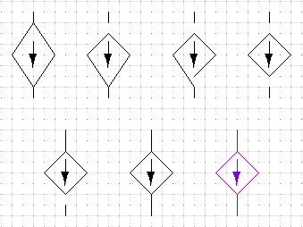
Steps in editing the user-defined object.
This can be an incredibly useful feature for general drawing. A
wholesale use of it is necessary to create such extravaganzas as
this rendition of the
JHU Applied
Physics Lab's logo. I have made use of something in PostScript
known as a ``path,'' that is, a linked set of lines, arcs, and splines
which together form the boundary of a single object which can be
bordered, filled, colored, etc. In this task, I will show you how
to generate a picture of a solid cylinder, by making a path consisting
of both ellipses and lines.
- Start with a clean page.
- Create an ellipse as follows:
- Type macro a to start an arc.
- Drag the arc out to some desired size.
- Click the first mouse button three times (to bypass endpoint
editing and go to ellipse axis editing). The position of
the cursor will move from the side of the circle to the top.
- Drag the ellipse minor axis to the desired size and click
the second mouse button to end.
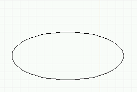
Creating a path object (solid cylinder): top ellipse.
- The whole ellipse becomes the top of the "cylinder". To make the
bottom of the cylinder:
- Copy the first arc and place it well below the first.
- Type macro e to edit (or select edit from the menu
and click on the lower ellipse).
- Immediately type e again or click on the first mouse
button to go to endpoint editing mode.
- Drag the endpoint around to the other side until the
result is the bottom half of an ellipse. Click the
second mouse button to finish.
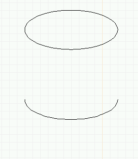
Creating a path object (solid cylinder): bottom (half) ellipse.
- Draw two lines to create the sides of the cylinder.
- Select the bottom and sides of the cylinder, and type the j key
to "join" these segments into a single "path".
- Select everything. If you (individually) select any component of the
path (either the side lines or the bottom ellipse), the whole path
will be highlighted.
- Copy (with the c macro) and place the copy to the side.
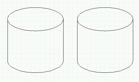
Creating a path object (solid cylinder): Two cylinder frames.
- Select the path (lower part) of the rightmost cylinder.
- Choose menu item "Options->Elements->Fill->(black box)". Now
you can see how to create arbitrary filled shapes.
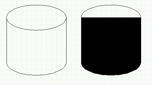
Creating a path object (solid cylinder): Two cylinders, the right one
consisting of a filled path.
- Finish the cylinder in the following manner:
- Color the path shape dark gray.
- Select the ellipse located above the colored cylinder and
perform the same steps to make it filled solid and colored
light gray.
- Use the X keyboard macro to correctly arrange the
elements, with the light gray ellipse on top of the dark
gray path object.
- Place the black wire frame cylinder on the left on top of
the solid cylinder on the right. Hint: Move the
wire frame halfway on top of the solid cylinder, then
arrange the top-to-bottom order of the elements so
that the wire frame ends up on top, then move the
wire frame the rest of the way.
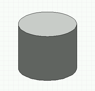
Creating a path object (solid cylinder): Finished cylinder.
By now you should understand the basic user interface of xcircuit and be able
to get around the menus, the drawing area, be able to handle the popup
prompting windows, load and save files, write text, and create polygons,
arcs, curves, paths, and user objects. Of course, we have just touched
the surface of xcircuit capabilities. The list of features below
will help you find out all the things that can be done with the program.
For help with remembering keyboard macros and their functions, select the
menu item "Options->Help!". You will get a popup window to the right of
the screen which lists all of the available keyboard functions. Tap the
"Done" bottom at the bottom when you no longer need the help menu.
 Back to the xcircuit home page. . .

email: tim@bach.ece.jhu.edu


 A purple polygon
  More purple polygons.
 Some differenct arcs.


 The load-file popup window.


![]() Back to the xcircuit home page. . .
Back to the xcircuit home page. . .
![]()